 "Torquelife" (torquelife)
03/25/2015 at 17:45 • Filed to: None
 15
15
 9
9|
"Torquelife" (torquelife)
03/25/2015 at 17:45 • Filed to: None | 15
| 9 |
Aerodynamic forces can be broken down into two simple categories: lift (good) and drag (bad). In the context of a car, we want our lift to be pointing down, so it's more commonly referred to as downforce. The primary tool for achieving this is a well-designed wing.
!!! UNKNOWN CONTENT TYPE !!!
Find more !!!error: Indecipherable SUB-paragraph formatting!!! content at !!!error: Indecipherable SUB-paragraph formatting!!! and on Twitter !!!error: Indecipherable SUB-paragraph formatting!!! . !!!error: Indecipherable SUB-paragraph formatting!!!
!!! UNKNOWN CONTENT TYPE !!!
!!! UNKNOWN CONTENT TYPE !!!
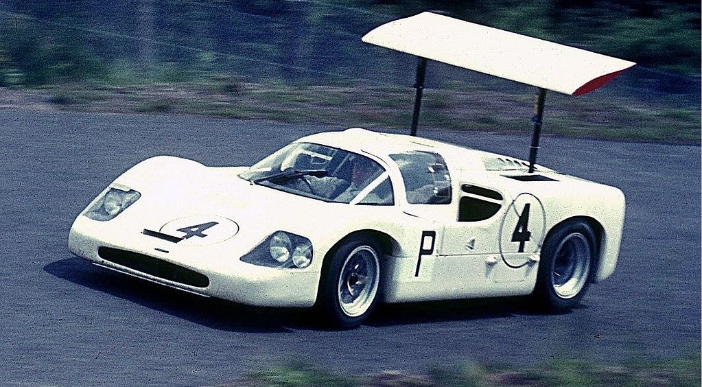
The iconic Chaparral 2F at the Nurburgring in 1967. Image: Wikipedia/Spurzem ( !!!error: Indecipherable SUB-paragraph formatting!!! )
!!! UNKNOWN CONTENT TYPE !!!
Aerodynamic forces can be broken down into two simple categories: lift (good) and drag (bad). In the context of a car, we want our lift to be pointing down so it's more commonly referred to as downforce. The primary tool available to achieve this is a well-designed wing. Now we're all aware of wings to some degree; if you're as lucky as I am, you got stuck in traffic today behind a Civic with a wing on its trunk that I'm pretty sure was made out of cardboard.
However, when well-designed and properly implemented, wings can truly be a thing of beauty. But how does a wing actually work? In very general terms, a wing produces downforce by creating a pressure difference between the top and bottom surfaces of the wing. The pressure difference is due to the fact that air is accelerated differently between the top and bottom surfaces of a wing.
There are a lot of theories and explanations behind why and how wings work but most of them are impractical; they're either too mathematically tedious for everyday use or overly simplified which can lead to a misunderstanding of the physics. In fact, one of the most common explanations I hear is actually just dead wrong. A lot of people try and explain airfoils by saying that the travel time has to be the same for air going around the top and the bottom of the wing so if one side is longer than the other, there is a resulting velocity difference and also a resulting force. The problem with this theory is that there is nothing that dictates this behavior. It's possible to go through and mathematically show that this theory doesn't match up with real world numbers but there's an easier way to show that this theory is false. Let's go with the easy way since I don't actually like doing math. Simply put, there is no reason for this to be true. There are a couple laws of nature, like "heat flows from hot things to colder things" or "things that go up eventually come down" but no mechanism for distinguishing particles for each other. How would a particle of air know that it was supposed to meet this specific particle and not some other one at the end of the wing?
A better explanation that works within a certain set of assumptions is "thin airfoil theory" which is based on very specific type of fluid behavior called potential flow but again, I don't like math so let's skip the rigorous proof and go with a simpler, visual explanation of how lift is produced.
Imagine that we have a symmetric airfoil at a 0° angle of attack, as shown below. Since it is a symmetric airfoil, the air flowing over the wing is exactly the same as the air flowing under the wing. At this point, there is no downforce being produced, but there is drag being produced from the friction of air rubbing against the surface of the wing as it flows over it. Also, there is a bright red spot right at the front of the airfoil, which we'll call the leading edge. This red spot is where air meets the airfoil head on and comes to a stop, otherwise known as a stagnation point.
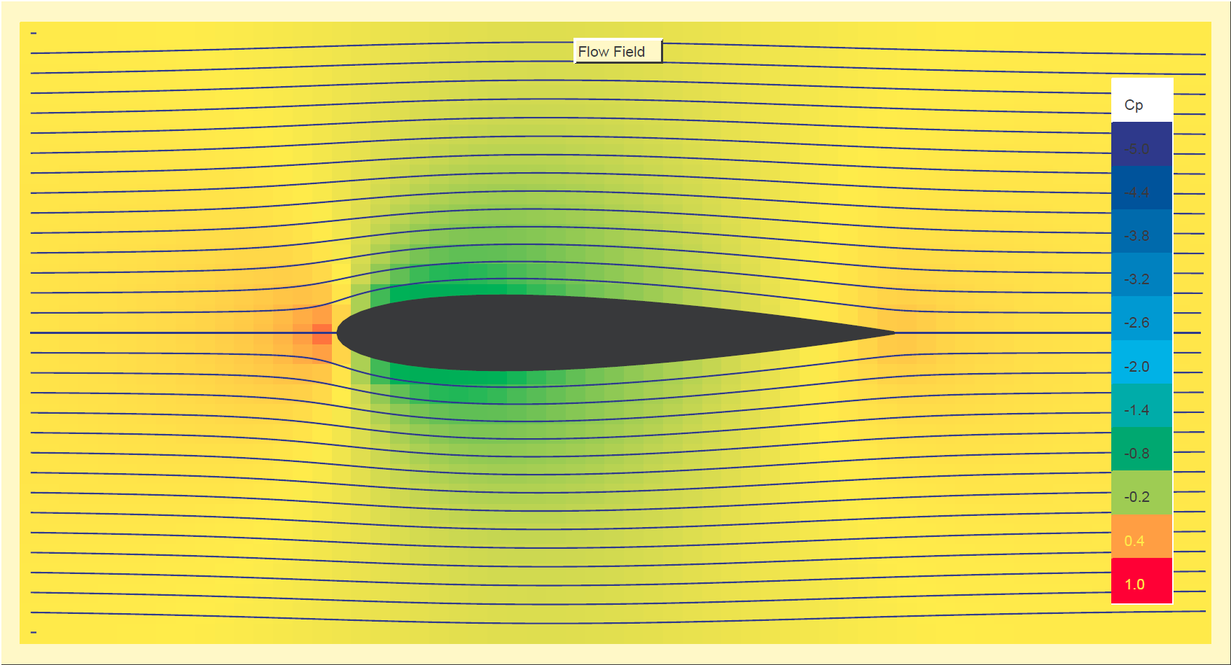
Flow field around a symmetrical airfoil at 0 angle of attack
!!! UNKNOWN CONTENT TYPE !!!
The figure is just a screenshot of a free program called JavaFoil, created by Dr. Martin Hepperle, and I highly recommend trying it out for yourself. I used the default airfoil geometry and under the Flowfield tab, selected the Colored Field, Streamlines, increased accuracy, and Pressure Coefficient options. The colors represent the "coefficient of pressure", Cp, which is a way to depict the pressure at a certain area relative to the freestream pressure. For example, the red area at the front of the airfoil corresponds to a Cp of one, meaning that there is no air velocity there and pressure is highest at that point. The other colors depict Cp less than one; notice how there are identical blotches of green above and below the airfoil. Also, the lines around the airfoil are called streamlines; these represent how the air flows around a body. The streamlines are identical above and below the airfoil. This is all expected because I picked a symmetrical airfoil to analyze.
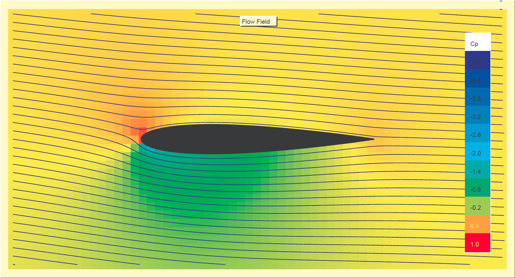
Now let's take this same airfoil, and tilt it downwards a bit so that things are no longer symmetric about the horizontal axis. Air still accelerates along the wing, but in a different manner now that there is a negative angle of attack. For air hitting the airfoil above the stagnation point, it accelerates away from the freestream air to follow the topside of the airfoil. The flow below the stagnation point also accelerates, but it must accelerate more dramatically because of the negative angle of attack. Rather than turning only a little bit, the air actually has to turn downwards and then back up in order to follow the underside of the wing. The airflow is illustrated below in the flow field made with JavaFoil.

Flow field around a symmetric airfoil at -5 angle of attack
!!! UNKNOWN CONTENT TYPE !!!
The way JavaFoil visualizes angle of attack is by changing the direction of the incoming airflow and not angling the airfoil which is why the airfoil is still horizontal. However, the plot still illustrates the main points. There is a stagnation point like before but shifted a bit towards the top side of the airfoil. Also, the streamlines show that the flow turns more on the underside of the airfoil than the topside so air must accelerate more on the underside.
If the airflow around the top and bottom of the airfoil is accelerated differently, then Bernoulli's Principle tells us that there is a pressure difference between the top and bottom of the wing. This is supported by the pressure plots; the Cp above the airfoil is all in the -0.2 to 0.4 range while below the airfoil, it is in the -0.8 to -1.4 range. The pressure difference results in air pushing down on the wing, producing a net force which gives us our downforce. The force vector will not be oriented perfectly downwards, but angled in a way so that it adds to the drag force. This additional drag force is commonly referred to as the lift-induced drag, and is a cost associated with making downforce.
There are several sources of drag, with the primary ones being parasitic drag and induced drag. Parasitic drag can further be broken down into more specific categories like form drag, which is sometimes referred to as pressure drag, and viscous drag due to skin friction. Just for completeness, there are a few additional types of drag that we don't need to worry about, such as wave drag, but it is worth being aware of them. Wave drag can be thought of as a more intense version of pressure drag that results from the presence of a shock wave. Since cars very rarely reach transonic and higher speeds, shock waves aren't really a big concern.
As a quick side note, there are a lot of names and types of drag that I'm throwing at you and to make it worse, the naming convention can be inconsistent. From talking to different professors, or reading different textbooks and websites, I've noticed that the names people use for different types of drag can vary wildly. So I'll do my best to stick to what I believe is the most common convention.
Flow field around a symmetrical airfoil at -5 angle of attack
The major sources of drag that we are concerned about are actually pretty self-explanatory. Viscous drag, which is also known as friction drag, comes about from the air rubbing against the surface of our airfoil. That's simple enough. Then there's pressure drag, which is due to the pressure difference at the front and back of the airfoil. If the image looks familiar, that's because it's the same one from when we were discussing lift above. But if you look at the distribution of the coefficient of pressure (Cp), you'll see that the highest Cp is at the leading edge of the airfoil and it quickly decreases. This means that air at the front of the airfoil is pushing harder than the air at the back of the airfoil which results in an overall force pointing backwards. Both viscous drag and pressure drag grow as you move faster.
Things get a little more interesting when we start considering three dimensional effects like vortices, which are the main driver of induced drag. Up to this point, I haven't really made a distinction between 2D and 3D wings but there is a fairly significant effect you get in 3D that you don't in 2D. Generally speaking, there is a high pressure side and a low pressure side of the wing, as seen in the Cp distribution above. At the ends of a wing, air from the high pressure side can "leak" over to the low pressure side of the wing. This results in the air swirling and becoming a vortex. This process is illustrated in the image below.
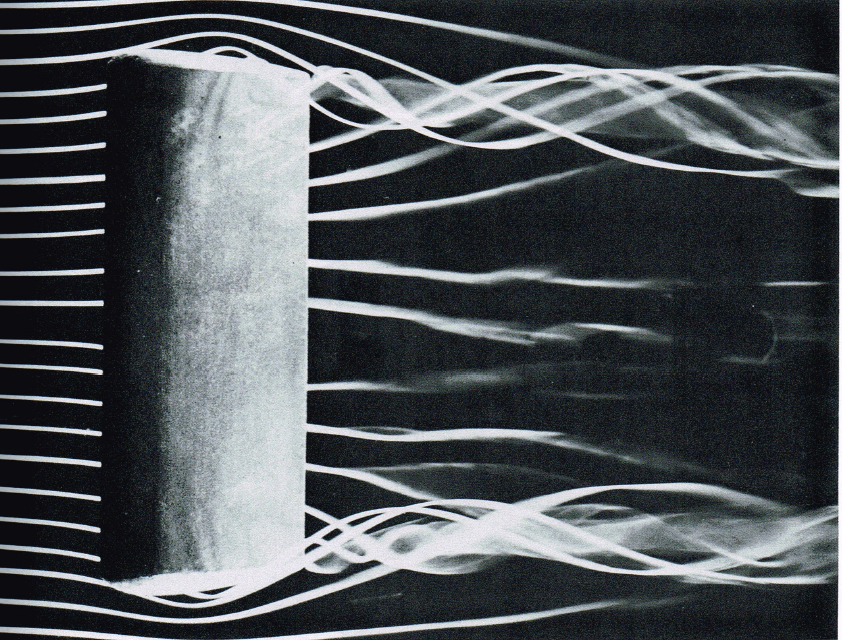
Smoke trail visualization of wingtip vortices. Source: An Album of Fluid Motion/Milton Van Dyke ( !!!error: Indecipherable SUB-paragraph formatting!!! )
I scanned this image out of "An Album of Fluid Motion" which is a fantastic compilation of flow visualization photographs. This particular photograph uses smoke trails to highlight the vortices at the wing tips. As air from the high pressure side flows around the wing to the low pressure side, it mixes with the air flowing past the wing so the overall air flow around the wing actually changes due to the vortices. So how do these vortices induce drag? As air gets mixed up with these vortices, the direction of the air flow changes and this deflection is known as downwash. The angle of this downwash is what dictates the angle that the overall force is tilted at so the more downwash there is, the more the force will be angled, meaning that the breakdown into the lift and drag components results in a larger drag component. Combining the parasitic and induced drag gives you the total drag.
Why is drag so important though? Since drag is a force directed in the opposite direction that you're moving, it can be thought of as a power loss which ultimately affects performance such as acceleration and top speed. Or, if setting a new lap record isn't your main priority, drag also affects your fuel efficiency and hits you in your wallet. Drag isn't always a bad thing though. For example, if you need a little help coming to a stop after reentering Earth's atmosphere, you can take advantage of drag by using some tools like air brakes or a giant parachute like the one pictured below.
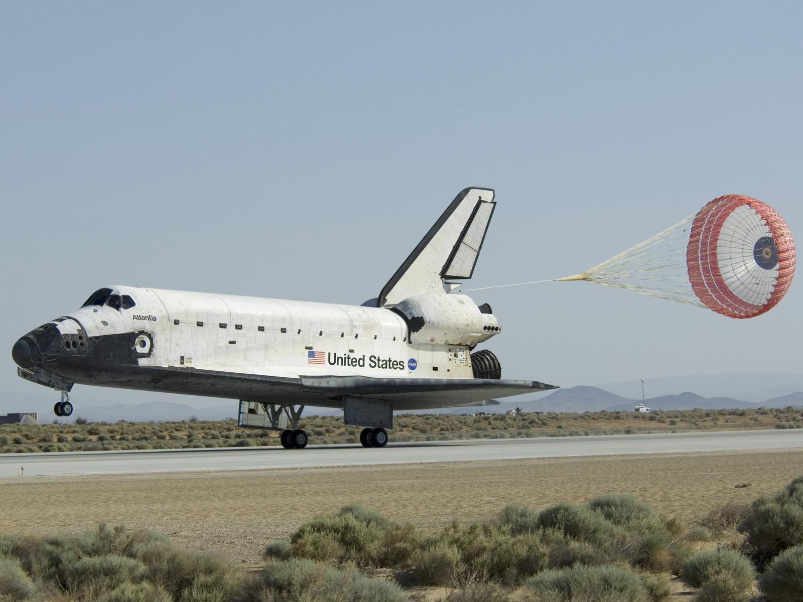
Space Shuttle Atlantis touching down at Edwards Air Force Base. Image: NASA/Carla Thomas ( !!!error: Indecipherable SUB-paragraph formatting!!! )
!!! UNKNOWN CONTENT TYPE !!!
!!!error: Indecipherable SUB-paragraph formatting!!! is a new editorial venture focusing on the technical side of the automotive world, written by current and former automotive engineers. Find out more and follow our latest content at !!!error: Indecipherable SUB-paragraph formatting!!! or on Twitter !!!error: Indecipherable SUB-paragraph formatting!!! .
 For Sweden
> Torquelife
For Sweden
> Torquelife
03/25/2015 at 17:52 |
|
This will replace any text written by Anderson.
 Shoop
> Torquelife
Shoop
> Torquelife
03/25/2015 at 17:52 |
|
You should talk about underbody downforce that comes from the air going under the car, and the purpose of diffusers and stuff.
|
Torquelife
> Shoop
03/25/2015 at 17:57 |
|
We're getting there - there's a whole series of aerodynamics articles coming, including wing elements (single and multiple), diffusers, end plates, etc.
It's a vast field of study, and trying to cover so many things in one article would result in a textbook ;)
 uofime
> Torquelife
uofime
> Torquelife
03/25/2015 at 17:58 |
|
but what about camber, boundary layers and multi element design?
 MrDakka
> Torquelife
MrDakka
> Torquelife
03/25/2015 at 18:34 |
|
Great intro article, if you want some help, I've got a bunch of textbooks as references :)
Looking forward to upcoming articles
 NJAnon
> Torquelife
NJAnon
> Torquelife
03/25/2015 at 21:49 |
|
Didn't come for the wall of text!! came for that beastly Chapparal racing car torque!
kidding, good info.
 Gizmo - The Only Good Gremlin, but don't feed me after Midnight
> Torquelife
Gizmo - The Only Good Gremlin, but don't feed me after Midnight
> Torquelife
03/26/2015 at 00:15 |
|
I'll just leave this here for a later discussion.
https://www.facebook.com/video.php?v=80…
 PICKLEBOY
> Torquelife
PICKLEBOY
> Torquelife
04/03/2015 at 00:32 |
|
I feel so excited that I knew about the terms and equations like bernoullis and vortices that you mentioned as I am currently taking my Fluid mechanics class which is pretty challenging, but it definitely helped me read your post haha
 Leon711
> Torquelife
Leon711
> Torquelife
04/03/2015 at 08:19 |
|
like hucho and his enormous textbook